| |
PT Cruiser Power Antenna Installation Guide
This is a procedure for a J.C. Whitney Power Antenna Installation on my 02 PT Cruiser.
Another brand of power antenna is advertised as being installable by an 8 year old in 2 hours,
this installation took two 50 + year old individuals about 4 hours to install.
Here's some information
on the antenna, which is available at the J.C. Whitney
web site. You can locate the antenna easily on the site by conducting a search using the part number.
Retailer: J.C. Whitney
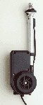
Product: Power Retractable AM/FM Antenna
P/N: 03ZX9414A
Finish: Satin stainless steel or black
Mast: 5-section, extends a full 39", retracts to 1"
Price: $39.95
Description:
Fully automatic AM/FM power antenna. Extra-short mast housing requires only 9-3/4" under-fender clearance for mounting. Raise and lower with a flick of your radio dial.
Comes with relay, 46" lead-in cable, and adjustable rocker-type mounting base to fit all fenders with slope from 0 to 30 degrees.
Includes mounting hardware, instructions. For use with all 12-volt negative-ground automotive systems.
Tools:
Flat Screwdriver
#2 Phillips Screwdriver
Torx Screwdriver
Sharp knife
Soldering Iron
Solder and Electrical Tape
3/8" wrench
17mm thinwall socket
10mm socket or wrench
Coarse file/grinder
Auto jack & jack stand
Materials:
2" velcro strips
Radio Shack Male-to-Female 24" Cable Cat.#: 12-1312
Installation Procedure:
- Remove the power window switch. This is pried off gently with a flat screwdriver. Be careful not to damage the switch while prying it off. It's not attached with screws or fasteners, and with a little effort it will
pop out. Once the switch is pulled out slightly, you will be able to see the attached wiring harness. Look for the RED tab where the wiring attaches to the switch. Disengage this tab and remove or unplug the wiring harness. Then remove the switch and set
it aside.
- Remove the air conditioner vent knobs. These pull directly off. Remember to set the
switches straight up so you can replace them the same way you took them off.
- Remove one Phillips head screw in the top of the console trim. This screw is located
directly where the window switch was located. After removing this screw, you can
pull the console off with a good tug.
- Remove the 4 Phillps screws holding the radio in the dash and pull out the radio
to where you can access the rear wiring plug. This is where the power
wiring for the antenna operation will be attached.
- Open the glove compartment and pull in on the foam rubber stops in order to
lower the drawer to the floor.
- Open the passenger side door and remove the lower door sill scuff plate
and kick panel by manually pulling them up from their snapped down position.
- The relay that comes with the power antenna is now ready to be installed. Place the antenna relay behind the left glove compartment support and attach, with a 2" strip of velcro tape on the back of the relay,
by pressing against the metal support.
- The antenna relay has five wires connected to it:
Route to Radio:
White: Fused - connect to radio rear plug on/off power switch.
Black: Ground - connect to the radio chasis.
Blue: Power - connect to the radio connector.
Route to Antenna:
Red: Power - connect to the antenna.
Green: Power - connect to the antenna.
- Feed the white, black and blue relay wires to the center dash area for attachment to the radio. Feed the red and green relay wires across the bottom of the dash,
and under the glove compartment towards the kick panel area for attachment (antenna power) to the antenna.
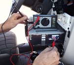
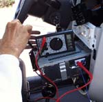
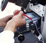
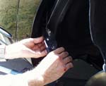
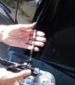
- Remove a 1/4" length of insulation on the red wire exiting the radio connector and attach the blue relay wire to it, then fasten and tape securely. This wire is (+) always hot. (See photo 1.)
- The white fused relay wire is placed into the top second pin from the passenger side of the rear plug for the radio on/off switch power to the relay. (See photo 2 and 3.)
- The black relay wire with a ring terminal is then fastened under one of the rear case torx screws for (-) ground.
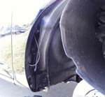
- Outside, in the passenger front wheel well, the inner fender splash panel needs to be removed and pulled out of the way. The front wheel can be turned to right lock to give some room or, as I did,
the front of the car can be jacked up and supported, and the front wheel can be removed completely for access to the splash panel area.
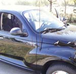
- The OEM stock antenna included with PT Cruisers is 32" in length, black, and has a non-collapsible metal fixed mast. In order to remove the OEM antenna you will need an open-end 3/8" wrench.
Place the wrench around the base of the antenna and gently turn it counter clockwise. It's a screw type mount and once unthreaded it should pull right out. (See photo 6.)
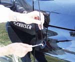
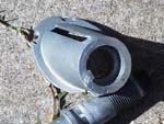
- Then remove the lower portion of the OEM antenna from the fender by loosening the cap nut with either the correct spanner wrench or by using a slot screwdriver and pounding with judicious care to not to slip
and scratch the fender until the cap nut comes loose. When the nut has been removed then pull the lower portion of the OEM antenna thru the splash panel area and cut the OEM antenna cable a few inches from the OEM antenna. (See photo 4 and 5.)
- I elected to cut the OEM antenna cable and to splice a universal antenna connector to the end because the radio end of the OEM antenna cable takes a rather uncommon antenna connector different from the one on the
universal power antenna. I can now remove and replace antennas at will using a multitude of universal antennas. (See photo 9.)
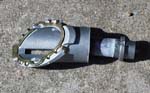
- To install the new power antenna in place of the OEM antenna the antenna base has to be modified for use with the new power antenna. The center antenna shaft needs to be removed from the base by using a hammer to pound it out of the base.
(See photo 7.) After removing the shaft from the base the bottom of the base needs to be filed/ground down about 1/16" of an inch for proper antenna locating in the fender. (See photo 8.)
- Place the new power antenna shaft thru the OEM antenna base and locate into existing hole in the fender, then place the outside antenna cap over the new antenna shaft and press down to the fender and lightly fasten in place
with the nut provided with the antenna kit.
Attach one end of the bracket strip provided in the kit to the bottom of the new antenna with the phillips machine screw provided in the kit. Bend the bracket strip to allow fastening to the lower fender mounting bolt. Remove the fender mounting bolt
place thru the end of the bracket and reattach to the fending mounting.
- Connect the antenna cable to the new universal connector, or splice the antenna cable to the OEM cable end.
Locate and pullout the OEM antenna cable grommet, that feeds thru the kick panel area, from the outside and place a small 1/8" incision to next to antenna cable and then feed the antenna power wires thru the grommet
and then feed them thru the hole into the interior kick panel hole.
Removing a lower dash panel fiber panel helps gain access to the hole and feeding a coat hanger or stiff guide
wire thru the hole and then taping the antenna wires to the guide can help in getting the outside wires to feed thru to the interior.
- Attach the new power antenna wires to the red and green relay wires that should be in the vicinity at the bottom of the glove compartment opening.
- Once the new power antenna wires are attached the installation can be tested. Turn the ignition to on or acc and turn on the radio, the antenna mast should extend an then shut off. Turning the radio off should lower the antenna mast and then shut off.
If this dosen't work go back and check all connections and fuses.
- Now secure the antenna to the fender by tightening the mast nut with a 17mm thinwall socket, and then checking for antenna angle in the fender by extending the mast and adjusting the lower mounting bracket as needed.
After securely tightening reinstall the inner fender well splash panel. Reinstall front wheel if removed and lower the car off jack.
- Reinstall passenger kick panel and door sill scuff plate. Replace the glove box foam rubber stops back in place and close door. Reinstall the radio with the 4 phillips screws. Reinstall the console trim and screw in place.
Reinstall the HVAC control knobs. Reattach window switches to connector and replace in dash.
- The installation is complete, sit back and admire your new power antenna. I haven't experienced any problems with the antenna or my reception since I installed it. I do listen with somewhat of a critical ear,
although it's not difficult to get good reception in Kansas.
1
 |
2
 |
3
 |
4
 |
5
 |
6
 |
7
 |
8
 |
9
 |
10
 |
11
 |
12
 |
13
 |
Universal Antenna Adapter:
I constructed the universal antenna connector out of the Radio Shack Male-to Female 24" cable by cutting the female end of the cable approximately 6-8" from the end and splicing it to the exisisting OEM antenna coaxial wire.
To splice the cables together:
- Cut and peel back the outer cover, outer shield and the inner insulation leaving about 1/4" bare conductor on each end.
- Splice the two conductors together by feeding each conductor into the opposite insulation and solder if desired.
- Tape to secure and cover the inner insulation. Then spread the outer shield back over the connection as best it can and cover with a 1"x 3" piece of tin foil and seal with electrical tape.
(The connection is secure and works just fine electrically.)
The Radio Shack Male-to-Female 24" Cable ($2.99) Cat.#: 12-1312 is available at your local Radio Shack store or their
web site.
Alternatively, there are crimp on coax connectors that could be used instead of the Radio Shack antenna connector cable. This would involve cutting the factory cable and attaching one connector to it
and then cutting the end off the power antenna cable and putting the opposite connector on it.
Also one could just cut the factory antenna cable and splice it directly to the power antenna cable with no connector involved.
This antenna modification was installed on 2002 PT Cruiser with a standard AM/FM/CD, w/o cassette.
Last Update 03/21/04
Hits: 
|
|


 Home
- Links
- Events
- Store
- Vendors
- Forum
- Specs
- Pics
Home
- Links
- Events
- Store
- Vendors
- Forum
- Specs
- Pics